Introduction
Welcome to our new blog series on “Why Electrical Engineering is Crucial to Data Centers”! In this first post, we’re covering one of the most important fundamentals of electrical design and installation: grounding and bonding. We’ll break down what each one is, why it matters, and what to look for in the field.
Grounding and Bonding
People use “grounding” and “bonding” interchangeably, but they are not the same thing and confusing them can lead to real problems.
Grounding is the connection to earth. Its job is to stabilize voltage and equalize potential throughout the building. When most people think “grounding,” they picture the pieces that tie the electrical system to the dirt: building steel, water pipe, ground rods, concrete encased electrode, and so on. That stuff matters, but it is usually not the thing that saves you in a fault.
Bonding is what actually clears a fault and keeps you safe. It creates a continuous, low impedance path for fault current to return to the source, so protective devices operate fast. If bonding is broken or incorrect, the fault current may not be high enough to trip the breaker quickly, which means energized metal, longer exposure, and higher risk.
In simple terms, grounding is about reference and stability. Bonding is about fault clearing.
For this article, our focus is bonding, because nearly every safety critical outcome depends on it. An important boundary to frame this discussion, we are talking about solidly grounded systems here. That means the system is intentionally designed with a low resistance fault return path so a ground fault produces high fault current, which in a properly coordinated system trips the upstream protective device and removes the fault quickly.
Separately Derived vs. Non-Separately Derived Systems
If you want to really understand bonding and apply it correctly, you have to start with how the electrical distribution system is built. Everything boils down to one simple question: Is there a direct electrical connection between sources?
If yes, you are dealing with a non-separately derived system.
If no, and the neutral connection is intentionally broken, then you are dealing with a separately derived system.
That one distinction drives where the neutral to ground bond belongs, and it is why these systems behave differently during a ground fault.
Separately Derived Systems
Separately derived systems exist when there is no direct electrical connection between two power sources, like a utility, generator, or transformer. The most common way this happens is when the neutral is intentionally switched during transfer between utility and generator. If the neutral connection is broken between sources, the sources are no longer electrically tied together, so each source is treated as its own system. That is what “separately derived” means.
In the field, you’ll typically see this with a 4-pole switching device, like a 4-pole ATS or a 4-pole breaker. When we say 4-pole, we mean the neutral is switched along with the phase conductors in a 3-phase system.
In the image below, the utility and the generator feed a load through a 4 pole automatic transfer switch. Because the neutral is switched, the sources are not electrically tied together through the neutral. That means this is a separately derived system.
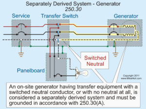
What does that mean for bonding?
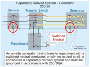
It means you need a neutral to ground bond at each source. The bond at the service and the bond at the generator are circled in red below. That is the correct bonding setup for a separately derived system.
To illustrate that this works, let’s look at a faulted scenario from each source.
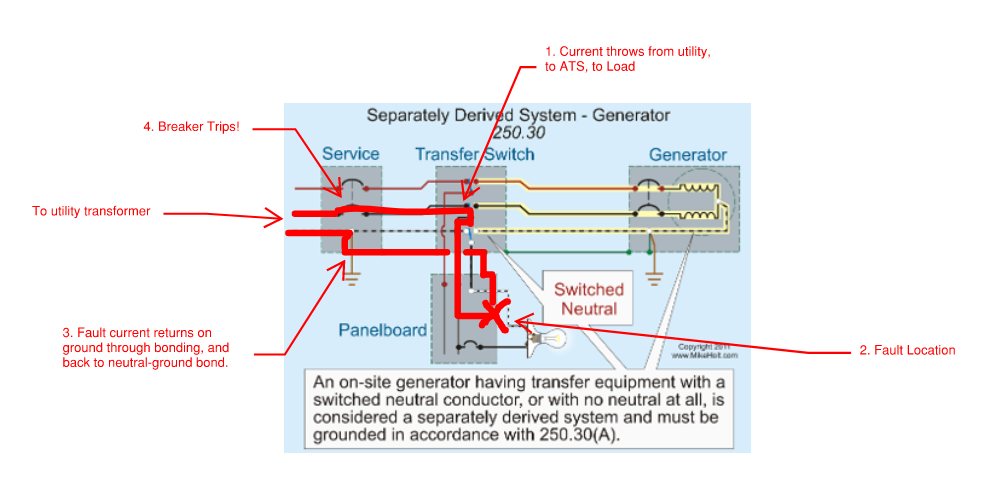
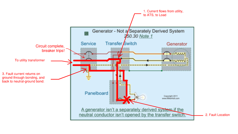
Why this works (utility source, faulted)
System state: ATS is on utility.
Fault: A phase to ground fault occurs at a panelboard enclosure.
Fault current path:
Enclosure → equipment grounding conductor → service neutral to ground bond → neutral conductor → back to source
Because the neutral is switched in the ATS, there is no parallel path back through the generator. The return path is clean, intentional, and low impedance. That produces high fault current, and the protective device trips quickly.
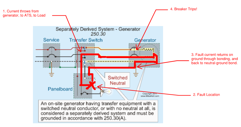
Why this works (generator source, faulted)
System state: ATS is on generator.
Fault: A phase to ground fault occurs at a panelboard enclosure.
Fault current path (simple version):
Enclosure → equipment grounding conductor → generator neutral to ground bond → neutral conductor → back to generator neutral (source).
Same story. That bond completes the circuit, fault current rises fast, and the breaker trips quickly.
What happens if you do this wrong (missing bond on separately derived)
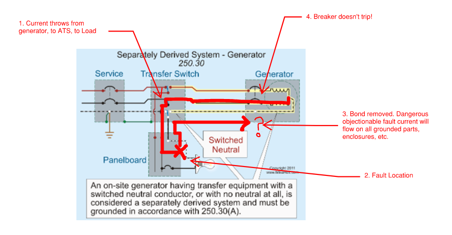
Let’s look at a separately derived system where someone removed the neutral to ground bond at the generator:
System state: ATS is on generator. Neutral is switched.
Fault: A phase to ground fault occurs at a panelboard enclosure.
What happens:
The fault current can get onto the equipment grounding system, but it cannot return to the generator source because the neutral is switched and there is no neutral to ground bond at the generator.
No effective return path means low fault current. Low fault current means the breaker may not trip. And “nothing happens” is not a good nothing.
This is how you end up with energized enclosures, building steel, and equipment grounds during a faulted condition until someone finds the problem and clears it.
Non-Separately Derived Systems
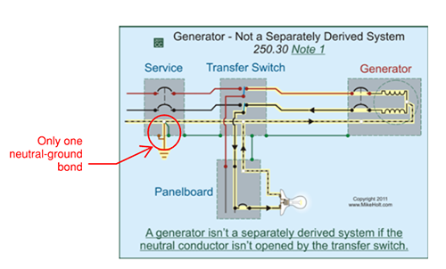
Non-separately derived systems have a direct electrical connection between sources, most commonly through a continuous neutral. This is typical with a 3-pole ATS where the neutral is solid and not switched. Because the sources remain connected, you must have only one neutral to ground bond between those sources. In most facilities, that bond is at the service entrance equipment, supplied by the utility transformer.
Why this works (utility and generator, faulted)
In a non-separately derived system, the neutral is continuous, so the system has one intentional neutral to ground bond. That single bond serves as the fault return reference regardless of whether you are running on utility or generator.
Fault current path:
Enclosure → equipment grounding conductor → service neutral to ground bond → neutral conductor → back to whichever source is operating.
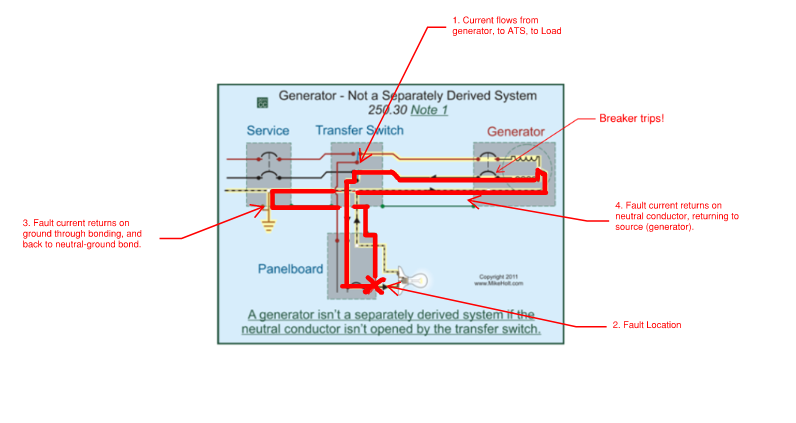
This is why the single bond rule matters. With a solid neutral, you do not want multiple bonds creating parallel return paths
Additional Bond in a Non-Separately Derived System
There are two major ways this goes wrong. We already looked at one – missing bonds in a separately derived system. The second is having extra bonds in non-separately derived system.
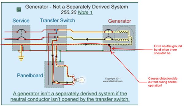
Multiple neutral to ground bonds create objectionable current. That means current flows on equipment enclosures, building steel, and other normally non-current carrying metal parts during normal operation. The system may “work,” but you have created shock risk, unexpected arcing potential, and a troubleshooting nightmare.
One of the most common causes is leaving the generator’s factory installed neutral to ground bond in place when you aren’t switching the neutral.
Most generators ship with a neutral to ground bond installed by default. If the neutral is not switched, that bond often needs to be removed. If it is not removed, you now have multiple bonds and multiple parallel paths.
And current does not only flow on the path of least resistance. It flows on all available paths.
Normal current path with an extra bond:
Fault current path:
Source → load → neutral conductor → unintended neutral to ground bond → equipment grounding conductor and bonded metal (enclosures and steel) → back to the main neutral to ground bond → back to source
Missing the required bond on a separately derived source can prevent ground faults from clearing properly, leaving equipment energized in a faulted condition.
Bottom line: you have to know what type of system you have before you decide what to do with neutral to ground bonds.
What to Look for in the Field
Here is a quick, practical checklist from a commissioning and site walk perspective. Grounding and bonding issues are rarely hidden, but they are routinely overlooked.
- Start with the drawings
-
- Review the one line and grounding details and decide if the system is separately derived or non-separately derived.
- Ask the simple question:Is there a direct electrical connection between sources, usually through the neutral?
- Look for the transfer method: 3-pole or 4-pole.
- 4 -pole means the neutral is switched.
- 3-pole means the neutral is solid and continuous.
- Verify the equipment matches the design
- Compare submittals to the design intent.
- Confirm the ATS or breaker is actually furnished as a 4-pole. This will be indicated on equipment nameplates.
- Find the neutral bar, ground bar, and any bond
Once you are in front of the gear…- Identify the neutral bar and the ground bar in each major piece of equipment. Particularly service entrance switchgear, transformers, and generators.
- Look for any neutral-ground bonding jumper, strap, or bus link.
- In service equipment and some transformer sections, you will often see a physical bar or strap tying the neutral to the ground.
- Decide whether that bond belongs there based on Step 1. If it does not, it needs to be removed or relocated per the design.
- Check the generator bond specifically
This is one of the most common field misses.- Open the generator termination section where the power conductors land.
- Look for a factory installed connection from the generator neutral to the equipment ground.
- If the system is separately derived (neutral switched, 4 pole), that bond typically stays.
- If the system is non-separately derived (neutral not switched, 3 pole), that bond typically must be removed by the generator technician to avoid multiple neutral to ground bonds and objectionable current.
- Sanity check the installation
- Confirm consistency between design, submittals, and what is actually installed.
- Watch for simple mistakes that create an unintentional second bond:
- Grounds landed on neutral bars
- Neutral and ground bars tied together in more than one cabinet or section
-
- If anything is unclear, pull in the equipment vendor or startup tech and make them walk you through the factory intended bonding configuration and the field modifications required.
- Confirm labeling and documentation
- Look for clear labeling of bonding jumpers or straps inside switchgear, generators, and transformers.
- If labeling is missing, add it. The next person will thank you.
These checks should happen before the system is energized. Bonding mistakes are far easier to correct early than after the system is live, loaded, and operating.
Final Takeaway
The most important lesson is simple: bonding, not grounding, is what makes electrical systems safe.
If you understand whether the system is separately derived, know where bonds belong, and verify those bonds in the field, you can prevent unsafe conditions, nuisance issues, and failures to clear faults.
When in doubt, sketch the system with the neutral-ground bonds you see, trace the fault current path back to each source under normal operation as well as faulted scenarios, and confirm there is one, and only one, intentional neutral to ground bond where the design requires it.
Conclusion
We hope you enjoyed our first blog post on electrical engineering in data centers. In future posts, we’ll dive deeper into topics such as arc flash labeling, UPS Systems, switchgear, what electrical engineers do, and more!
If you have a topic you would like to see us cover, please let us know!
And follow us on LinkedIn here.
Charlie Wlodyka, P.E.
President
TechSite